ProVPilot

Modding — Movable Parts ← Back to ProVPilot

ProVPilot › Modding › Movable Parts

Making movable parts in Blender 5

How to separate vertices out of a single merged 3D model, turn them into their own named part, move the pivot (origin) onto the hinge line, and — when needed — rotate the pivot axes so control surfaces such as ailerons, elevators and rudders deflect correctly in ProVPilot and Godot.

Why this matters

Many downloaded aircraft models arrive as one big merged mesh — the ailerons, elevator and rudder are baked into the airframe and can't move on their own. ProVPilot animates a control surface by rotating its node about the node's local origin. If the origin sits at the model centre instead of on the hinge, the part swings around the fuselage centerline instead of hinging at the wing.

So the job has three parts: (1) split the surface off into its own object, (2) give it a clear name, and (3) move the origin onto the hinge line (and rotate the origin axes if the hinge doesn't run along a world axis). After that, ProVPilot's animation code does the rest.

Step-by-step

1

Enter Edit Mode & isolate the surface

Select the merged airframe object in the viewport, then press Tab to enter Edit Mode. To see through the model while selecting, toggle X-ray with Alt + Z so you can box-select both the top and bottom skins of the surface at once.

Edit Mode on the merged model. Turn on X-ray to select through the mesh.
2

Select the vertices of the part

Switch to Vertex select (1). If the surface is a separate connected island, hover over it and press L to select linked — this grabs the whole island in one go. Otherwise box-select (B) around the front and back faces with X-ray on.
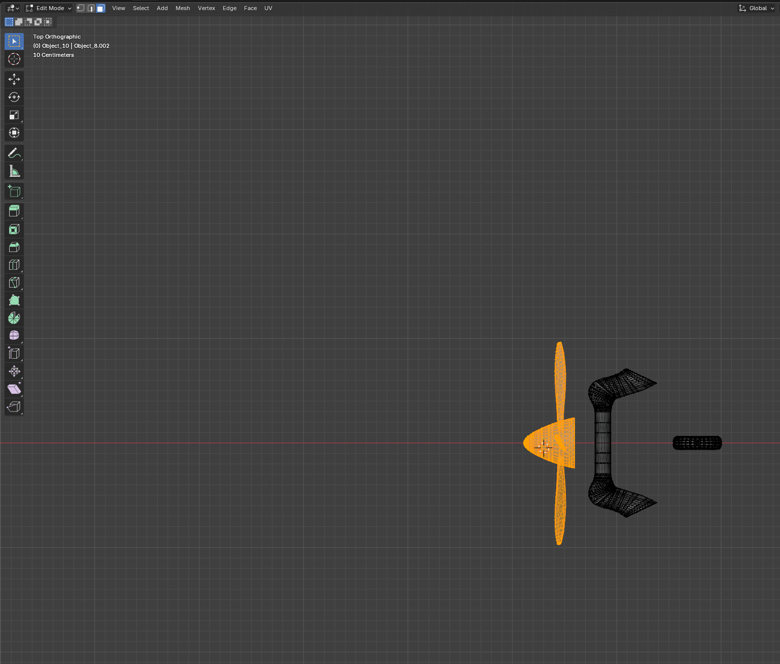
Selecting the vertices that make up the control surface
The control surface vertices selected (highlighted) and ready to separate.
Tip: L (select linked under cursor) and Ctrl + L (select linked from current selection) are the fastest way to grab a clean island without catching neighbouring geometry.
3

Separate them into a new object

With the vertices selected, press P to open the Separate menu and choose Selection. Blender pulls those vertices out into a brand-new object while leaving the rest of the airframe intact.
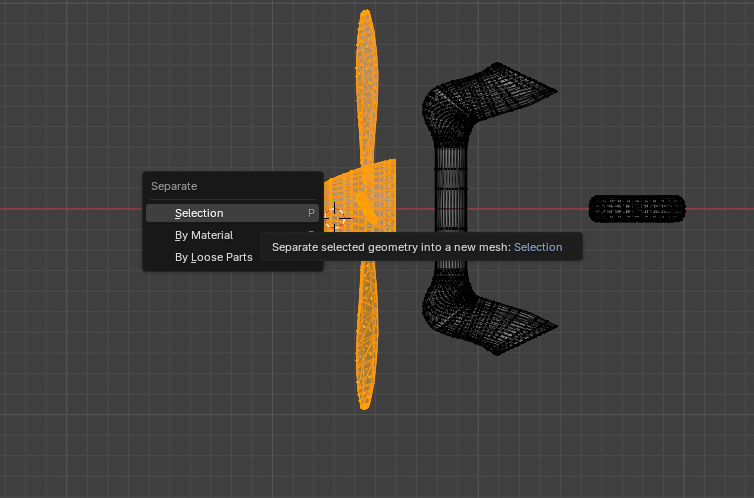
The Separate menu with Selection chosen
PSelection splits the surface into its own object.

Press Tab to return to Object Mode. The new part now appears as a separate entry in the Outliner.

4

Rename the new part

In the Outliner, double-click the freshly created object (it'll be named something like Airframe.001) and give it a clear, stable name — e.g. Aileron_R, Aileron_L, Elevator or Rudder. ProVPilot's aircraft config references parts by this node name, so keep it consistent.

Rename the part in the Outliner — this name is the node path ProVPilot animates.
Naming matters: avoid spaces and keep the exact spelling you'll use in aircraft.cfg. After the model is loaded the node path looks like Sketchfab_model/…/Aileron_R — the last segment is the name you set here.
5

Find & select the hinge edge

Now move the origin onto the hinge line. Select the new part, enter Edit Mode (Tab) and switch to Edge select (2). The hinge is the leading edge of the surface — the row of vertices nearest the wing (for an aileron) or the fixed structure.
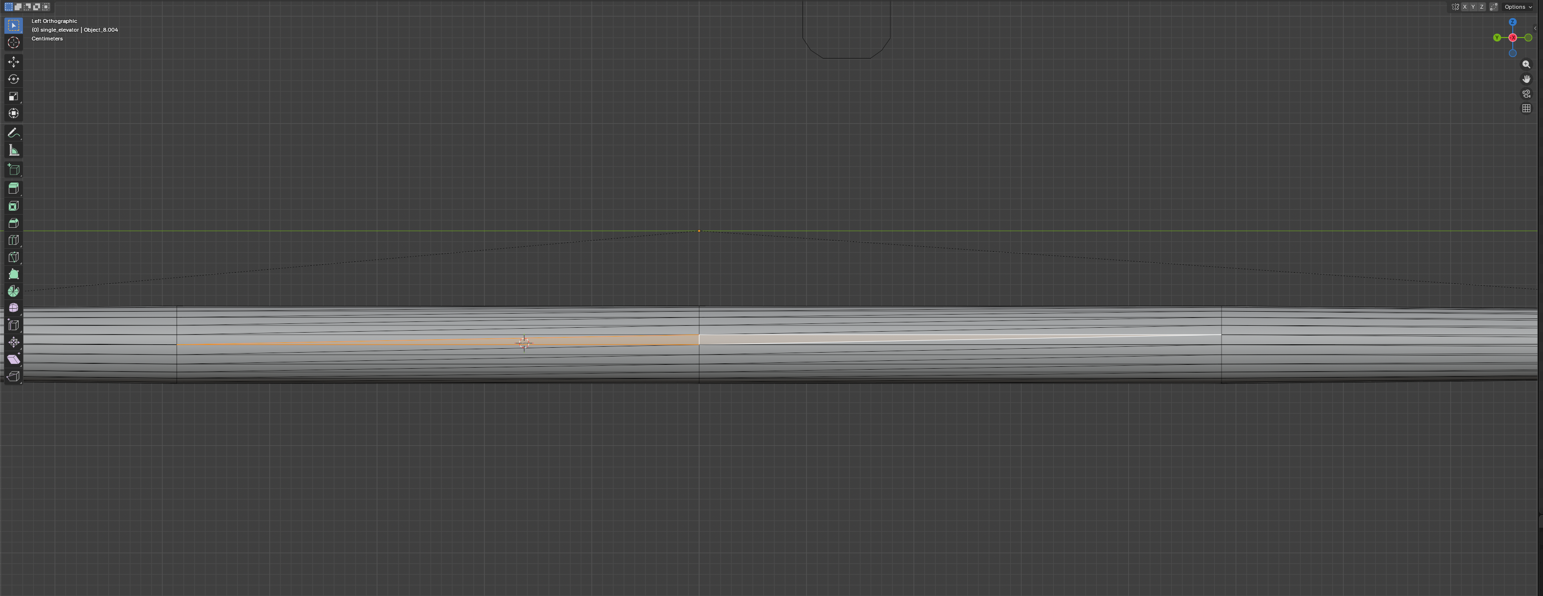
Snap pie menu — Cursor to Selected
Alt-click the hinge edge loop to grab the whole spanwise line at once.
How to spot the hinge: check the part bounds. For a typical right aileron the hinge runs spanwise (along the wing) and sits at the most-negative X edge (the edge nearest the wing root/leading edge). Alt + click an edge selects the entire loop along that line.
6

Snap the 3D cursor to the hinge

With the hinge edge loop selected, press Shift + S to open the Snap pie menu and choose Cursor to Selected. The 3D cursor jumps to the midpoint of those vertices — exactly where the hinge axis runs.
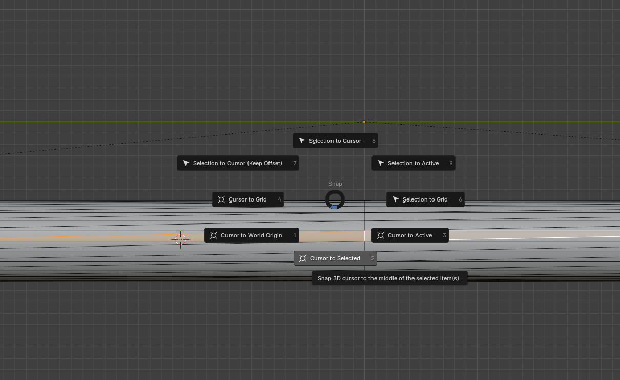
Selecting the hinge edge loop along the leading edge
Shift + SCursor to Selected places the 3D cursor on the hinge line.

Return to Object Mode with Tab.

7

Set the origin to the 3D cursor

In Object Mode, go to Object → Set Origin → Origin to 3D Cursor. The part's origin (its little orange dot) snaps onto the hinge line. This is the pivot ProVPilot rotates around — now it hinges at the wing instead of swinging around the fuselage centerline.
Object menu — Set Origin — Origin to 3D Cursor
Object → Set Origin → Origin to 3D Cursor moves the pivot onto the hinge.
Reset the cursor afterwards with Shift + C so it returns to the world origin and doesn't interfere with later snaps.
8

Rotate the pivot axes (only if needed)

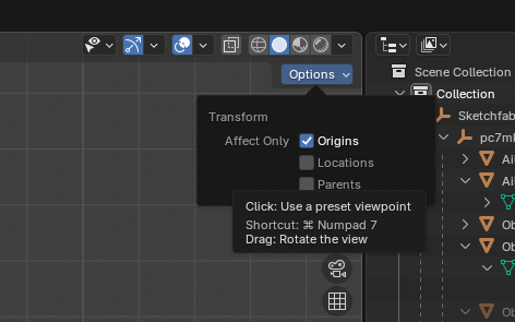
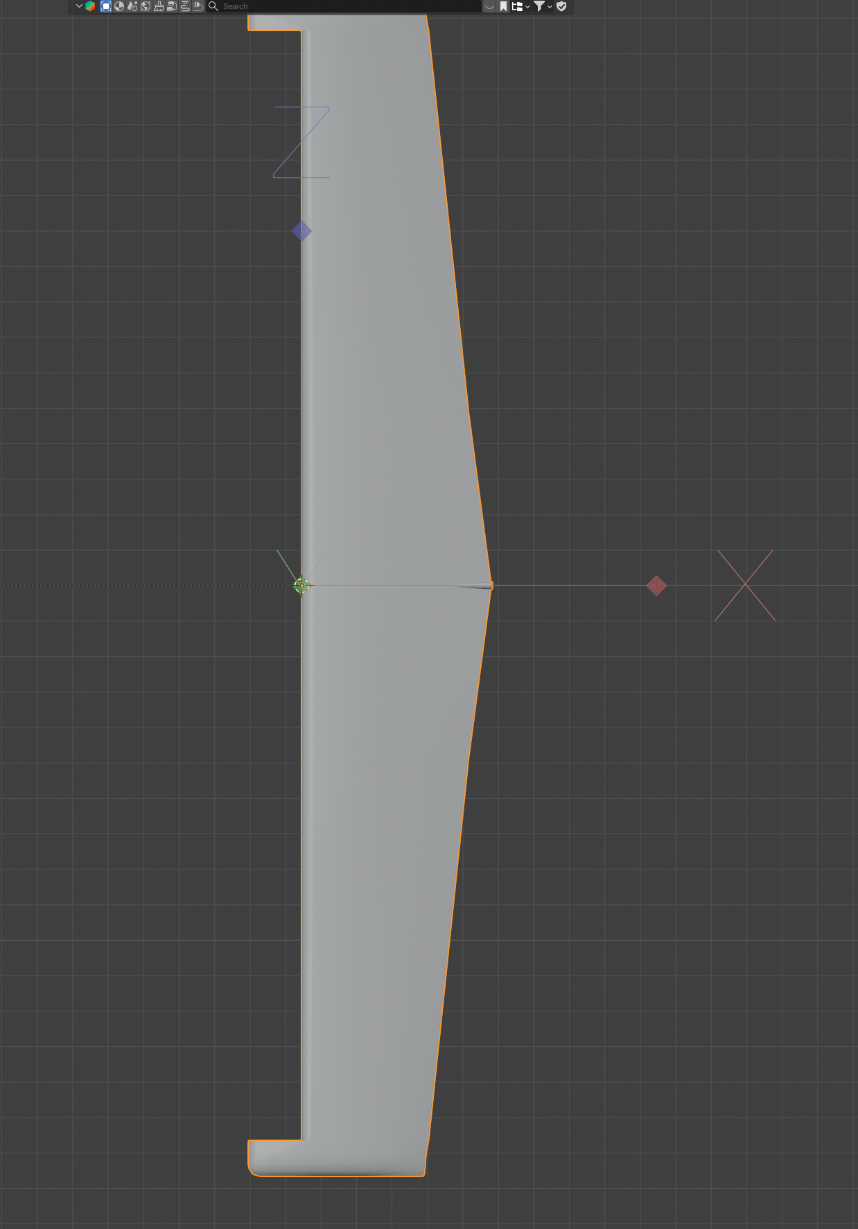
A control surface hinges about one axis — an aileron sweeps about the span axis so the trailing edge moves up and down. If your hinge line doesn't run cleanly along a local axis, you can rotate the origin's axes (without moving the geometry) so one local axis lines up with the hinge sweep.

Open the Options dropdown (top-right of the viewport) and enable Affect Only → Origins. Then press R and rotate so the chosen local axis matches the hinge sweep. Turn Affect Only Origins back off when you're done.
Affect Only Origins option enabled while rotating the pivot
Enable Options → Affect Only → Origins, then R to align an axis with the hinge.
The finished part: origin on the hinge line, local axis aligned with the hinge sweep.
Don't have to be perfect: ProVPilot applies the deflection about the node's local axis. As long as the origin is on the hinge and the part keeps its native orientation, it rotates correctly. If a surface ends up hinging about the wrong axis in-sim, that's a one-line config tweak (aileron_hinge_axis / elevator_hinge_axis / rudder_hinge_axis in aircraft.cfg) — no re-export needed.
9

Export & verify

Re-export the model to glTF (e.g. pc7_edited.gltf). The new part should carry a translation equal to the hinge position — proof the origin moved. You can verify on the .gltf alone before regenerating the runtime .glb: inspect the node and confirm the surface node now has the expected hinge translation.

# Inspect the exported node translation (proof the origin moved)
# Each separated surface should report a translation on its hinge line.
Texture reminder: if your .gltf references external textures by URI, keep those image files next to the .gltf when regenerating the .glb, or the rebuilt model comes out untextured.

Once the pivot is set, a single [animation] entry pointing at the new node path lets you watch the surface deflect in-sim.

Quick recap

  1. Edit Mode (Tab) on the merged model, X-ray (Alt + Z) to select through it.
  2. Select the surface vertices — L for a linked island.
  3. PSelection to separate into a new object.
  4. Rename it in the Outliner to a clean, stable name.
  5. Edit Mode → Edge select (2) → Alt-click the hinge edge loop.
  6. Shift + SCursor to Selected.
  7. Object Mode → Object → Set Origin → Origin to 3D Cursor.
  8. (If needed) Affect Only Origins + R to align an axis with the hinge.
  9. Re-export and verify the surface node carries the hinge translation.

Source & aircraft configs live on gitlab.md80.ch.